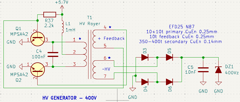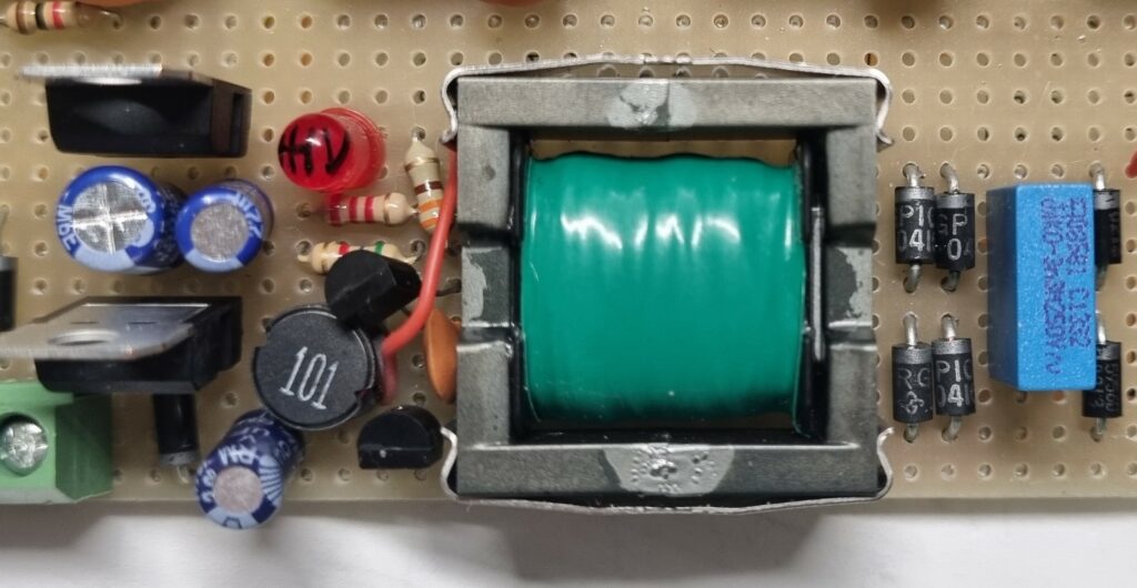
I’d like to present a simple high voltage converter primarily designed for powering Geiger tubes, though it can be adapted for different voltages and purposes. The circuit is based on the Resonant Royer topology, which is a self-oscillating converter known for its simplicity and efficiency. It uses two transistors operating in push-pull configuration with a feedback winding to maintain oscillation.
Circuit Description
The design uses a pair of MPSA42 transistors, though common alternatives like BC547 or 2N2222 can be used. The 2.2k Ohm resistor provides base bias for both transistors and determines the current draw. This value should be selected by monitoring both output voltage and input current – if the resistance is too high, the output voltage will drop. The optimal point is reached when you achieve the desired output voltage with minimal input current. In my implementation, the circuit draws 40mA at 5.7V input.
The resonant frequency is determined by the LC parallel circuit formed by the transformer’s primary inductance and the 100nF capacitor connected between the collectors.
Transformer Design
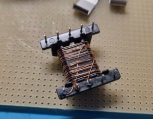
The transformer design isn’t based on complex calculations but rather on empirical rules that I’ve found to work reliably:
Primary Winding
- Always use 10+10 turns
- Wire gauge should be selected based on required current capacity
- Current can be calculated from input voltage and output power requirements
Feedback Winding
Turns ratio varies with input voltage:
- For 5V input: 10 turns
- For 9V input: 6-8 turns
- For 12V input: 4-5 turns
The feedback turns are crucial: too many turns risk damaging the transistors with excessive base drive, while too few turns result in incomplete switching, causing higher power consumption and poor conversion efficiency.
Secondary Winding
The secondary turns calculation follows this logic:
- Being a sinusoidal oscillator, the input waveform has a peak-to-peak amplitude of twice the supply voltage (due to the push-pull configuration)
- Calculate the turns ratio based on required output voltage
- Example: For 400V output from 10V input:
- Ratio needed = 400:10 = 40:1
- With 10 turns on primary, secondary needs 40 × 10 = 400 turns


Note: While the primary actually has 20 turns total (10+10), calculating based on just 10 turns empirically works. This might be because the actual transformation ratio depends on the inductance ratio between secondary and primary rather than turns ratio, but I haven’t investigated this aspect further.
The beauty of this design lies in its simplicity and adaptability – it can be modified for different voltage requirements while maintaining good efficiency.
