This project stems from my experience in searching for radioactive minerals such as pitchblende, torbernite, and autunite in the field. Deposits of these minerals can be found in Italy, particularly in the Alpine region. For instance, the pitchblende mine in Novazza, located in the Orobie Alps, features waste piles from tunnel excavations that are accessible without significant restrictions. However, these waste piles are situated in the mountains, along steep trekking paths.
To search for minerals in such conditions, one needs lightweight, robust (hence simple and reliable), and economical equipment (in case of breakage). High sensitivity to natural background radiation is unnecessary. The area of interest has a natural background radiation level varying from 0.3 µSv/h to 3-3.5 µSv/h, especially where the pitchblende vein naturally surfaces in striking black-streaked cliffs.
Given my previous experiences with self-built Geiger clickers, SV500s, various commercial Geigers, NaI(Tl) scintillators, and similar gadgets, I didn’t hesitate to create a device tailored for this specific purpose and environment using salvaged parts.
The following videos will show you how the device works and how is made.
Design:
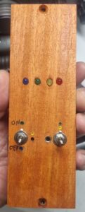
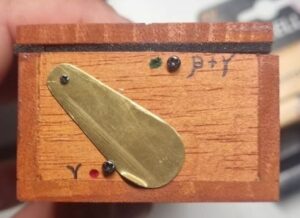
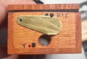
In Italy, design comes first, followed by functionality! I found some small, lightweight wooden planks made from a tropical wood called “Ayous,” which is slightly heavier than Balsa but much sturdier. The box is shaped into a lacquered cherry-colored rectangle with a brass sheet radiation filter at the front.
Behind the filter is a Philips 18550 Geiger tube with a mica window facing the filter. A 12mm diameter hole in the wooden wall holds the tube, which is protected by the brass sheet (for gamma) or exposed (for beta). The tube is glued inside the box with silicone.
The front panel features a 4-LED VU meter of different colors, a hole for the “click” sound (from a small internal speaker), two switches (on-off and clicker on-off), and a 3.5mm jack socket for connecting standard stereo headphones. The overall look is “steampunk.”
The electronics are assembled by salvaging parts from old electronic boards, including some compact fluorescent lamps (CFLs). Specifically, CFLs with E27 bases contain a 2.2-2.7mH inductor that I modified by adding two windings of 6 and 20 turns with wire-wrap wire to create a transformer. Additionally, the base contains HV diodes and capacitors used for the voltage multiplier stage. The transistor used to drive the transformer is also taken from the same CFL base, an MJE13007.
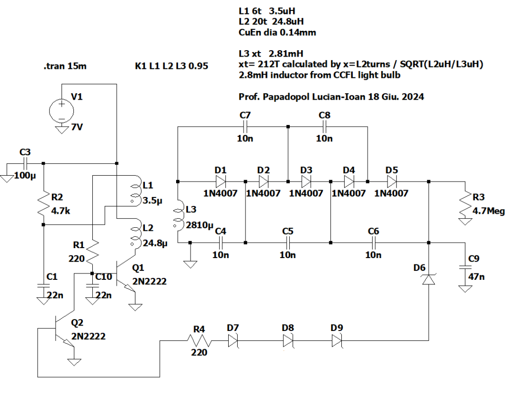
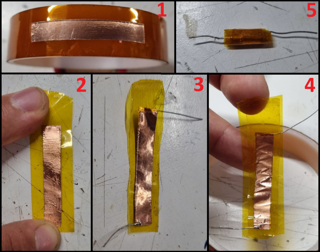
For extracting pulses from the Geiger tube, I followed the Philips datasheet, taking them from the anode. Since I didn’t have the necessary 22pF 1kV capacitor, I made one using Kapton tape as the dielectric and adhesive copper tape as the plates, rolling them into a cylinder. Knowing the thickness of the Kapton and its dielectric constant, it was straightforward to cut two plates of the appropriate area, which in my case, I recall, was around 1cm².
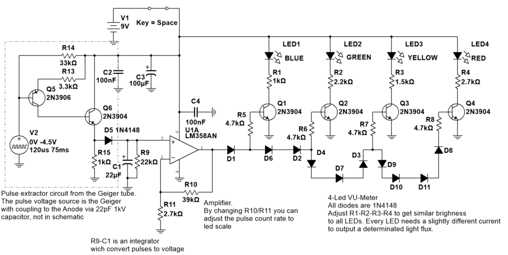
The transistor-based VU meter circuit provides immediate visual feedback, and combined with the “click click” sound, it is extremely effective in indicating the presence and intensity of a radiation source. The tube, being mainly sensitive on the mica window side, offers excellent directionality.
For those looking to replicate this project, be aware that the VU meter circuit behaves strangely. It doesn’t work in the Multisim simulator but functions perfectly in real life. Another tip: adjust the VU meter by varying the amplifier stage gain, i.e., R10/R11, to set the blue LED to light up at the desired radiation threshold.
There are some other modifications I can do too. The circuits could be improved and simplified, and I can replace LEDs with miniature low-current light bulbs. During usage, I’ve found a problem: the “clicker” volume is not enough for speakers, but perfect for headsets. For this reason, I’ve not published the circuit of the “click” generator.
Here is a picture collage that shows how I’ve made my 22pF 1kV capacitor.
You can see that using copper tape and Kapton tape makes the building process extremely easy.
The capacitor in the pictures has a couple of nF, and the “1kV” breakdown voltage is not tested yet, but Kapton is known for its extremely high breakdown strength. The ends of the capacitor body are filled with epoxy, not shown in the pictures.