Introduction
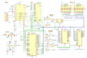
I have enhanced my Z80-based system with dual HPDL2416 intelligent displays. Each HPDL2416 is a sophisticated display module containing four 5×7 dot matrix alphanumeric displays with built-in ASCII decoder, memory, and multiplexing circuitry. This article details the hardware integration, address decoding logic, and programming interface.
Hardware Configuration

System Overview
The display subsystem consists of:
- 2 × HPDL2416 four-character intelligent displays
- Address decoding logic:
- U8A, U8B (74LS32) – OR gates
- U3E (74HCT04) – Inverter
- U9A (74LS139) – 2-to-4 decoder
Memory Mapping
The displays are mapped into the Z80’s I/O space from 08h to 0Fh:
- Display B: 08h-0Bh (when A3=1, A2=0)
- Display A: 0Ch-0Fh (when A3=1, A2=1)
Address Decoding Analysis
Address Decoding Structure
The address decoding uses different address bits for distinct purposes:
- A7-A4: Must be 0000 for I/O space selection
- A3, A2: Display selection logic
- A1, A0: Direct connection to displays for character position
Complete Address Decoding Map
| I/O Address | Binary | A3 A2 | A1 A0 | Selected Display | Position |
|---|---|---|---|---|---|
| 08h | 0000 1000 | 1 0 | 0 0 | Display B | Rightmost |
| 09h | 0000 1001 | 1 0 | 0 1 | Display B | Center-Right |
| 0Ah | 0000 1010 | 1 0 | 1 0 | Display B | Center-Left |
| 0Bh | 0000 1011 | 1 0 | 1 1 | Display B | Leftmost |
| 0Ch | 0000 1100 | 1 1 | 0 0 | Display A | Rightmost |
| 0Dh | 0000 1101 | 1 1 | 0 1 | Display A | Center-Right |
| 0Eh | 0000 1110 | 1 1 | 1 0 | Display A | Center-Left |
| 0Fh | 0000 1111 | 1 1 | 1 1 | Display A | Leftmost |
Decoding Logic Analysis
Display Selection (A3, A2)
The combination of A3 and A2 determines which display is active:
| A3 | A2 | Display A | Display B |
|---|---|---|---|
| 0 | 0 | 0 | 0 |
| 0 | 1 | 0 | 0 |
| 1 | 0 | 0 | 1 |
| 1 | 1 | 1 | 0 |
Character Position (A1, A0)
A1 and A0 are directly connected to the displays for position selection:
| A1 | A0 | Position |
|---|---|---|
| 0 | 0 | Rightmost |
| 0 | 1 | Center-Right |
| 1 | 0 | Center-Left |
| 1 | 1 | Leftmost |
Boolean Equations
Display_Enable = A7·A6·A5·A4·A3    (Active when A7-A4=0000 and A3=1)
Display_B_Select = A3·A2          (Active for 08h-0Bh)
Display_A_Select = A3·A2          (Active for 0Ch-0Fh)
Programming Interface
The HPDL2416 displays are programmed using standard Z80 I/O instructions. Each character position is individually addressable using OUT instructions.
Example: Writing “3K SIST.”
        .ORG $0000       ; Program start

    DI                   ; Disable interrupts

    ; Write to Display B (08h-0Bh)
    LD       A,'.'       ; Rightmost character
    OUT      ($08),A

    LD       A,'T'       ; Center-Right character
    OUT      ($09),A

    LD       A,'S'       ; Center-Left character
    OUT      ($0A),A

    LD       A,'I'       ; Leftmost character
    OUT      ($0B),A

    ; Write to Display A (0Ch-0Fh)
    LD       A,'S'       ; Rightmost character
    OUT      ($0C),A

    LD       A,' '       ; Center-Right character
    OUT      ($0D),A

    LD       A,'K'       ; Center-Left character
    OUT      ($0E),A

    LD       A,'3'       ; Leftmost character
    OUT      ($0F),A
Technical Implementation Notes
Hardware Considerations
- Address Decoding:
- Clean separation between displays using A3,A2
- Direct position selection through A1,A0
- No additional position decoding required
- Timing:
- No wait states required
- Direct memory-mapped interface
- Characters can be written at full Z80 I/O speed
System Benefits
- Hardware Simplification:
- Built-in character generator
- Integrated refresh circuitry
- Simple 5V power requirement
- Software Interface:
- Direct I/O addressing
- No complex initialization required
- Standard Z80 OUT instructions
Conclusion
The HPDL2416 integration provides an elegant solution for alphanumeric display in Z80 systems. The simple address decoding scheme, using A3/A2 for display selection and direct A1/A0 connections for position selection, results in a clean and efficient design. The straightforward programming interface makes it an excellent choice for applications requiring reliable alphanumeric display capabilities.